DC-SCM, Microwatt and OpenBMC
- Jeremy Kerr
- Matt Johnston
- dc-scm
- microwatt
- openbmc
- fpga
- linux
- bmc
- librebmc
- openpower
We recently built a fully open source Baseboard Management Controller (BMC) implementation, right down to the hardware, and used it to boot and manage an IBM POWER9 AC922 ("witherspoon") server. The AC922 platform is the compute component of the Summit and Sierra supercomputers, the two fastest worldwide until mid-2020.
This work was conducted in conjunction with the OpenPOWER foundation, as part of their libreBMC project, and builds on a lot of prior work from IBM and Antmicro.
Doing this all from scratch would be a massive effort, so we're standing on the shoulders of giants here, namely:
-
The Antmicro Artix DC-SCM hardware - an open hardware implementation of the Open Compute DC-SCM module, using an Artix FPGA as the core
-
The "AC922 Interposer" - an adapter between the AC922's baseboard and a DC-SCI connector.
-
Anton Blanchard's Microwatt project, implementing a fully open powerpc core, as gateware suitable for the Artix.
-
System-on-Chip peripherals using gateware from the LiteX project -
litesdcard,liteeth, andlitedram. -
LPC controller gateware, from Michael Neuling and Anton Blanchard, as part of the OpenPOWER Foundation's LibreBMC project.
-
A Linux kernel with a few extra drivers and platform configuration for Microwatt and the DC-SCM board.
-
An OpenBMC userspace, ported from the existing witherspoon platform definition.
Our work here was mainly to integrate these parts; a few fixes here and there, plus a few new features at various places in the stack.
There are a few other projects implementing a similar platform:
-
The original "boxarty" project from Joel Stanley, Paul Mackerras and Michael Neuling from IBM, an original prototype replacing the AC922's AST2500-based BMC board (codenamed "boxelder") with an Arty A7 FPGA prototyping board with Microwatt gateware. This was running a set of scripts to boot the AC922 host.
-
The Axiado / Antmicro boxarty updates, which built the original boxarty into a more reproducible embedded system using a buildroot port.
However, this is the first implementation (that we're aware of!) that runs a close-to-production OpenBMC stack, and uses a DC-SCM module.
Finally, this document provides an early snapshot of the project; we will keep things up-to-date as things progress, and/or as issues are fixed or the source code is updated.
Hardware🔗
The hardware components for this are:
- The Antmicro DC-SCM module
- An Antmicro Root of Trust (RoT) bypass board (we're not using a RoT on this platform).
- The AC922 interposer module
- The AC922 server itself
If you're following along at home, you'll also need:
- Some industrial hearing protection
- because we're working on pre-fan-control firmware, and the AC922 fans running at full speed are, well, industrial.
We needed a few reworks to the hardware to fix a few bugs and incompatibilities. Those are, in roughly-decreasing order of complexity:
Rework #1: LPC connectivity🔗
The version of the DC-SCM board that we're using does not connect the DC-SCI's ESPI channel to the FPGA, due to an intentionally non-populated component: a voltage translator between the 3.3V signals of the FPGA, and the 1.8V signals of the ESPI bus.
We have documented this at issue #2 of the DC-SCM repo. If/when that issue is fixed, this rework will not be necessary.
On the POWER9 platform, we use LPC rather than ESPI, and re-use those ESPI pins for the LPC connection to the host. In its current state, we can't interface the Artix FPGA to the LPC bus due to the unpopulated voltage translator.
Fortunately, we don't actually need voltage translation here, and can connect the 3.3V FPGA IOs to the DC-SCI directly.
This does require a rework though, bypassing the missing translator (refdes U21 in the design):
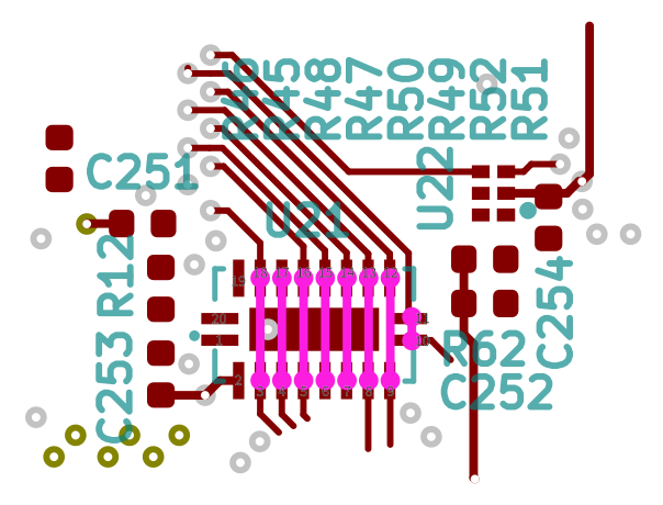
Unfortunately the pads on U21 are just a little too fine for the rework equipment we have. So, wrote up some instructions and had the friendly folks from Electronic Assembly Pty Ltd do the rework for us. Those instructions are available at dc-scm-rework-1.v1.pdf if you'd like to replicate the modifications.
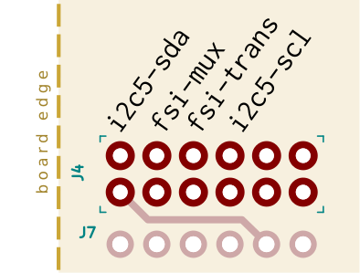
Rework #2: DC-SCM i2c5 routing🔗
There's an off-by-two error in the DC-SCM board, where pins for I2C bus 5 are out-of-place, and are instead connected to PCIe signals on the Artix.
We have documented this at issue #1 of the DC-SCM project, which is now fixed in the design.
In the meantime, we have cut the two traces for the A11 and A12 lines on the DC-SCM board, just inboard of the DC-SCI connector.
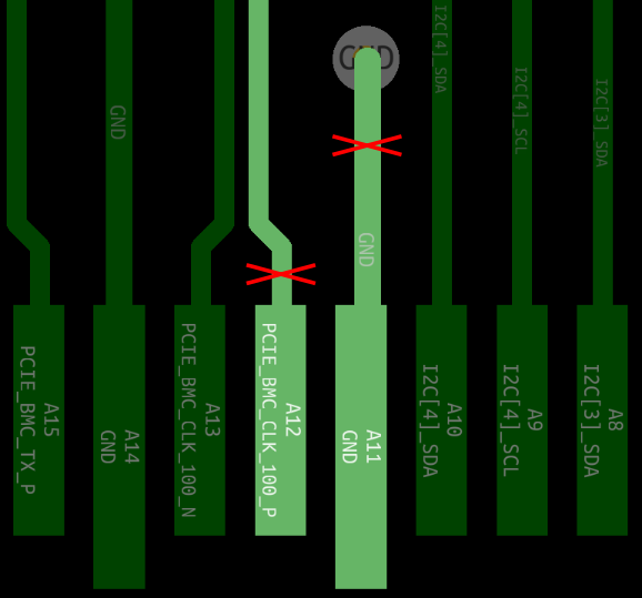
Note that these traces are on the back side of the board; the board diagram is flipped to show the traces as they appear on this side.
Since we still need the i2c5 bus connected, we have used some spare IO pins on the TPM header, and routed those to the i2c5 SDA and SCL signals. There are corresponding gateware and device tree updates to use those TPM pins as GPIOs (for i2c5), covered below.
Rework #3: Interposer FSI mux signal routing🔗
The AC922 interposer connects the baseboard's FSI mux input to pin B51 of the DC-SCI connector, which is a USB signal, and so not routed to the FPGA.
We have filed an issue on the interposer design for this.
To work around the issue, we have connected pin E4 of the molex connector to another FPGA IO on the TPM header.
However, the USB controller still drives this signal, so we need to isolate the USB controller device from the trace. There are a couple of options here: masking the pins on the DC-SCI connector, or isolating a single trace on the DC-SCM board.
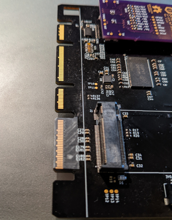
We went for the former, as it's less intrusive, and the issue is with the interposer rather than the DC-SCM. Since none of the signals in that same section of the DC-SCI edge connector are used, we can just mask the entire section with ESD-safe insulating tape:
Alternatively, you may isolate this one signal by cutting the USB trace on the DC-SCM board, near U18.
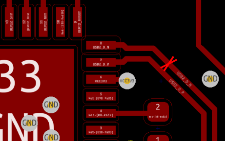
This is quite close to the USB_DP trace, but that is unused on the AC922
hardware - so any "collateral damage" from cutting both traces is likely to be
fine - provided you're not planning to use the DC-SCM board with other hardware.
Replacement IO🔗
In implementing the workaround above, we're replacing some existing (incorrect) connections with other FPGA IO lines. Since the TPM header is available, and connected directly to the FPIO IO banks, this gives us a convenient spot for our four replacement IO signals: two for i2c SDA/SCL, and two for the FSI mux/trans signals.
We have used the following pins on the board:
These can either be routed to corresponding pins on the back of the interposer's pin grid, or directly to the AC922 baseboard.
Other reworks🔗
We had a couple of issues with missing pins on the AC922 interposer board, which we have worked-around by using other spare FPGA IO pins (also on the DC-SCM TPM header), routed directly to the AC922 baseboard.
These should be contained to our particular hardware, but do check your own interposer for full pins on the 20x12 connector grid before going too far with debugging!
Gateware🔗
Microwatt gateware for the FPGA on the DC-SCM board can be found
in the
dev/dcscm
branch of our microwatt repo on github.
Building microwatt for the Artix FPGA is mainly described in Microwatt's
README.
In short, you'll need to set up fusesoc, and install Xilinx Vivado. In our
case, we used Vivado Free Edition 2022.1, but older versions should also work.
Build with:
The build will take around 10 minutes, and the resultant bitstream will
build/microwatt_0/antmicro-artix-dc-scm-vivado/microwatt_0.bit, ready to
load on the board. Alternatively, try our pre-built
bitstream: microwatt-dcscm-405c16a924.bit.
The micro-USB connector on the DC-SCM board provides JTAG access to the FPGA, and a Microwatt serial console. Connect this to your development machine to upload the bitstream to your DC-SCM board.
One of the board's 4MB NOR SPI flash chips is used to store the FPGA bitstream
and early software - this can be flashed using OpenOCD for JTAG, wrapped in the
flash-arty script to handle configuration. Behind the scenes flash-arty
loads a small
JTAG-SPI proxy bitstream
on the FPGA, to write to the flash chip.
If you specify the -l argument, the bitstream will be loaded directly to
the FPGA (rather than to flash), for a one-time boot. Use -x for a FPGA reset.
A serial console will show Microwatt's first stage loader running:
$ screen /dev/serial/by-id/usb-FTDI_Quad_RS232-HS-if02-port0 115200

Welcome to Microwatt !

 Soc signature: f00daa5500010001
 HDL Git SHA1: 405c16a924694a
  Soc features: UART DRAM SPIFLASH ETHERNET SDCARD
          DRAM: 512 MB
...
Trying flash...
Doesn't look like an elf64
HDR: ff ff ff ff ff ff ff ff
Copying payload to DRAM...
Booting from DRAM...
In this case, microwatt is up and running, but can't yet find software to load
from flash - that needs u-boot, which we'll add in the later u-boot
section.
The changes implemented in our microwatt port are:
LiteEth🔗
We have regenerated the LiteEth ethernet with a hardware reset to fix intermittent startup. This also required patching newer LiteEth to have stable register bank offsets (these are both ready pull requests).
The RGMII PHY chip on the DC-SCM also needs a zero delay, so a separate Microwatt config.
Extra GPIOs🔗
The BMC uses several I2C busses from the host for monitoring and control. We use the Linux GPIO bitbanging I2C driver for this, taking a SDA and SCL GPIO line per I2C bus.
Since there are 32 pins per GPIO bank, we added a second (GPIOB) bank at
0xc0008000 on the wishbone MMIO bus.
In future, the I2C functionality could be moved to gateware to avoid inefficient polling of GPIO by the kernel driver.
The interposer only connects a subset of the platform GPIO signals to the DC-SCI
connector, so there are some input signals that OpenBMC expects and are not
implemented in hardware. To work around this, we have added a few special GPIO
lines with fixed 0 or 1 values, so that certain missing hardware presence
lines can be emulated.
LPC gateware🔗
A LPC bus between host and BMC provides low-level interactions between these two components, including host firmware load, host serial console, and an IPMI channel.
The BMC LPC client is implemented through LPC gateware, originally provided by Michael Neuling and Anton Blanchard.
Amaranth was used to generate the verilog, no changes were required.
GPIO interrupts🔗
OpenBMC monitors GPIO interrupts, so we added support to Microwatt's GPIO implementation to trigger interrupts on input edges/levels, configurable by hardware registers.
SoC reset🔗
We have connected the SoC reset signal in Microwatt, triggerable by a syscon register.
LiteSDCard 1-bit data🔗
SD and MMC cards normally start in 1-bit data width mode and transition to wider modes after MMC host initialisation. LiteSDCard previously only supported 4 bit mode, so required driver workarounds to send an early "switch to 4 bit" command.
We have added support to LiteSDCard for 1-bit mode and switching at runtime, so the normal SD/MMC infrastructure can be used in u-boot and Linux. This should also support the 8-bit data width on the DC-SCM's eMMC, pending further testing.
Software🔗
The software architecture for the DC-SCM + OpenBMC setup is based on an fairly plain OpenBMC image, using the "witherspoon" platform. This is the production AC922 stack, using an AST2500 BMC. We have modified this for the Microwatt environment, plus hardware definitions for the DC-SCM board.
There are a couple of areas of storage available:
-
A small amount of SPI flash; we use this for the FPGA bitstream and the u-boot binary
-
A larger eMMC device; we use this for the OpenBMC image, including kernel and PNOR (host firmware) storage
The boot flow for the device is:
-
The FPGA bitstream is read from the on-board SPI flash
-
The bitstream contains a tiny loader implemented in BRAM (block RAM in the FPGA). This loader initialises the DRAM code, reads the u-boot image (also from SPI flash) into DRAM, and jumps to the
u-bootentry point -
The
u-bootbinary has a driver for the eMMC device, plus support for reading a kernel from theext4filesystem -
u-bootloads the Linux kerneldtbImagefrom a pre-defined path on an eMMC partition, and executes the kernel -
The Linux kernel has drivers for the eMMC device, which contains the OpenBMC root filesystem.
-
AC922 host firmware is kept on a separate partition on the eMMC device, as a simple 64MB flat file. This is loaded during the host power-on procedure.
All of the components for this project are available on github:
| Component | Repository & Branch |
|---|---|
| u-boot | u-boot dev/dcscm |
| Linux | linux dev/dcscm |
| OpenBMC | openbmc dev/dcscm |
Note that these branches are still in-development, and may be updated and rebased. The general trend will be for patches to go upstream, and we will update this document to correspond to any changes as they happen.
u-boot🔗
The u-boot port for the DC-SCM hardware is based on the general microwatt
port, by Paul Mackerras and Joel Stanley. This gives a base microwatt port,
including support for ethernet and SPI peripherals.
On top of this base, we have added support for the on-board eMMC device (to allow booting the kernel), added a general platform definition (a device tree and defconfig), and added some small features to make development easier.
The code is up at the dev/dcscm
branch of our u-boot
tree on github.
Building should just be a matter of:
the resulting image will be an ELF binary in obj.microwatt/u-boot; the
gateware can load and execute this directly from SPI flash.
To write this to flash, use the flash-arty script in the microwatt repository,
at the base address of 0x300000
$ ./openocd/flash-arty -c antmicro-artix-dc-scm -f a100 -a 0x300000 -t bin \
    ../u-boot/obj.microwatt/u-boot
Linux kernel🔗
The kernel port for the DC-SCM board is based on the general microwatt bringup work, plus a few OpenBMC-specific patches.
We have published our changes, based on a v6.0 upstream kernel, at the
dev/dcscm branch of
our linux tree on github.
The kernel .config is available here too:
linux-v6.0-dcscm.config. This also includes support
for a NFS root, which can be handy for initial development work - particularly
setting up the initial filesystem on the MMC device.
To build:
The DC-SCM kernel will build into a combined zImage + device-tree blob (a
dtbImage), located at
obj.microwatt/arch/powerpc/boot/dtbImage.microwatt-dcscm.elf.
If you need to alter the boot arguments, they are located in the
/chosen/bootargs property of the device tree source file, at
arch/powerpc/boot/dts/microwatt-dcscm.dts:
    chosen {
        bootargs = "root=/dev/mmcblk0p1";
        ibm,architecture-vec-5 = [19 00 10 00 00 00 00 00 00 00 00 00 00 00 00 00
                                  00 00 00 00 00 00 00 00 40 00 40];
        stdout-path = &UART0;
    };
for NFS booting, try something like:
bootargs = "root=/dev/nfs nfsroot=192.168.0.1:/srv/nfs/dcscm ip=dhcp";
- substituting IP and paths for your own environment, of course.
OpenBMC🔗
In order to get OpenBMC running on the DC-SCM board, we've added a new
witherspoon-microwatt platform definition, based on the original witherspoon
(ie., production AC922) platform. Anton Blanchard had created the base
support, and we have added further porting work to make a usable BMC image.
However: our main goal here was to prove the DC-SCM + microwatt components; this is still a long way from an upstreamable OpenBMC implementation. There are changes that are not suitable for the general repo, as they alter existing (working) components. So: treat this as reference code, rather than production!
The OpenBMC implementation is available from the
dev/dcscm branch of
our openbmc tree on github.
The build process is standard for an OpenBMC tree, just using the
witherspoon-microwat configuration:
The build infrastructure will download and build the OpenBMC components, and
assemble into an ext4 filesystem image, at:
tmp/deploy/images/witherspoon-microwatt/obmc-phosphor-image-witherspoon-microwatt.ext4
Deploying🔗
From here, we have a few components:
- The gateware, already flashed to the SPI device on the DC-SCM
- A u-boot build, also flashed to SPI
- A kernel, as a
dtbImage.elf - An OpenBMC image, as an
ext4filesystem image
The easiest way to assemble this into a full BMC will be to netboot the kernel,
using an embedded initramfs or small NFS root filesystem, and use that to set up
the MMC device. I would suggest a buildroot image for this; Joel Stanley has a
suitable tree in his microwatt branch of
buildroot.
From there, you can:
-
Create two partitions on the eMMC device (
/dev/mmcblk0):- One large one for the OpenBMC root filesystem
- One small (say, 200MB) for the host firmware
-
Write the OpenBMC
.ext4file to the first MMC partition -
Mount the new OpenBMC partition (
/dev/mmcblk0p1) -
Add the new kernel to the new partition: say, as
/boot/dtbImage.elf -
Create a new filesystem for host firmware on the second partition:
mkfs.ext4 -m 0 /dev/mmcblk0p1 -
Add a recent witherspoon PNOR to that new filesystem
-
Create a symlink from the OpenBMC
/var/pnor.imgto the PNOR image on the second partition
Using the two partitions will save time should you want to re-write the OpenBMC filesystem after a rebuild.
Then, set up u-boot to boot automatically:
=> setenv mmcboot 'ext4load mmc 0 0xc000000 /boot/dtbImage.elf; bootelf 0xc000000'
=> setenv bootcmd 'run mmcboot'
=> saveenv
And you should be good to go!
Of course, if you have any issues or queries, please get in touch with me, on jk@codeconstruct.com.au.
Future work🔗
This project was originally intended as a proof-of-concept of a full BMC running on the open source microwatt core, on the open DC-SCM hardware. We've reached that goal, but there are still a few components that would get us closer to a production-suitable BMC implementation.
General cleanups and upstreaming🔗
As this is mainly a proof-of-concept, some of the changes are a little rough-around-the-edges, so could benefit from a review and rework. There are also areas that can be optimised - both in the new code and the underlying codebases.
The main components of this work would be suitable for submitting upstream. We have a number of pull requests pending already, which will reduce the amount DC-SCM specific code needed.
Software optimisation🔗
In working through the stack for this implementation, we have identified a few areas that may benefit from some performance optimisation work. Parts of the OpenBMC stack are certainly designed for a higher-performance machine than the (current) microwatt core on the Artix FPGA, and there are definitely areas that would be fairly straightforward to start an optimisation effort on.
Gateware additions🔗
Currently, the FSI and I2C interfaces are implemented in software, so can be taxing on the CPU when there is traffic over those busses. With the system running, the full fan control implementation may use around 60%-80% of CPU just in FSI and I2C code.
The next step here would be to add hardware/gateware implementations of the FSI and I2C controllers; that would go a long way to reducing system load.
Easier deployment🔗
The current process requires a lot of manual setup to get an OpenBMC image constructed on the on-board storage. There could certainly be improvements to this flow; for example, implementing a small bootable image that automates flashing and initialising the OpenBMC system, or allowing easier access to the eMMC device for initial image loads.
Open synthesis tools🔗
In order to create the gateware bitstream, we're using the Vivado utility, which is free but not open; this is the only closed-source tool required for the whole stack. It would be great to add support for the Artix FPGA hardware to the existing open synthesis tools - yosys and nextpnr. Alternatively, we could look at using Lattice ECP-5 FPGA hardware instead, which is supported with a fully open FPGA toolchain, and can run microwatt.
If there's any area of development you would be interested in seeing, or participating in, please let us know!
Updates🔗
We'll keep this page updated as development continues; updates are listed below.
- 2020-10-20: Add more future work for synthesis tools